

Skip to content

What Is a Lightning Arrester and How Does It Work?

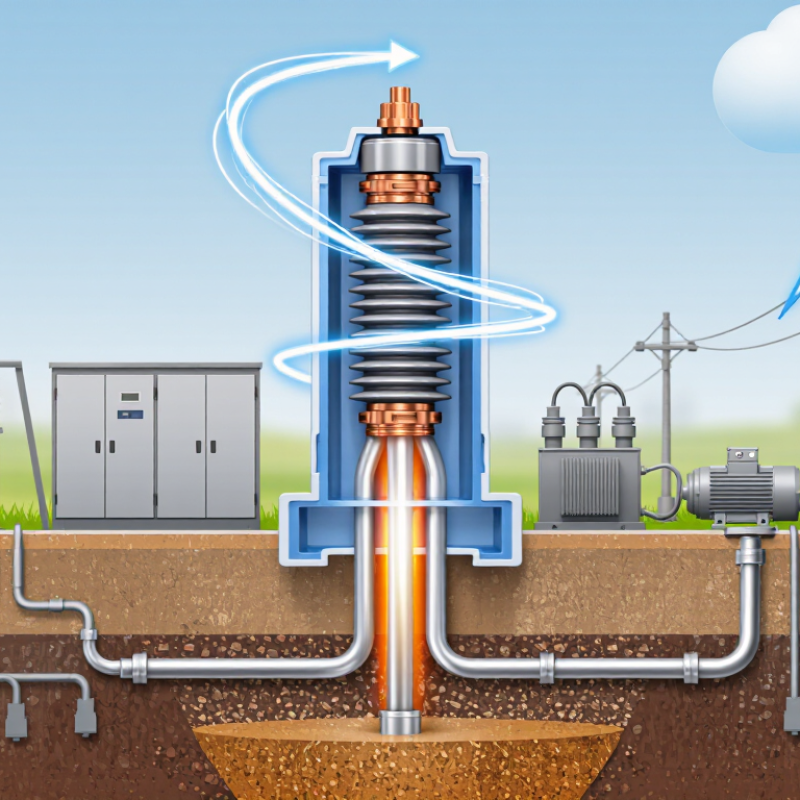
A Lightning Arrester is a protective device that limits dangerous overvoltage in electrical systems. It helps shield transformers, switchgear, motors, and sensitive control equipment from lightning impulses and switching surges. When voltage remains normal, the arrester conducts almost no current. During a surge, its metal-oxide elements become highly conductive. They guide excess energy toward earth, reducing the voltage stress across connected equipment. Then, they return to a high-resistance state.

This article explains what a Lightning Arrester does, how its internal components respond, and why installation details matter. A surge may last only microseconds, yet it can puncture insulation, damage circuit boards, or interrupt an industrial process. A short, straight connection to a properly designed grounding system improves performance. Long conductors can add inductive voltage and reduce protection effectiveness. Placement also matters. An arrester installed far from the protected equipment may leave part of the circuit exposed.

The discussion will refer to established engineering practices, including metal-oxide surge arrester principles described in IEC and IEEE standards. It will also distinguish arresters from lightning rods, fuses, and surge protective devices. These terms are often confused. They are not identical.

Real installations are less perfect than diagrams. Corrosion, aging, poor bonding, and incorrect ratings can weaken protection. I may simplify some electrical behavior for clarity. However, the practical limits remain important. A Lightning Arrester does not “stop” lightning. It manages surge energy and helps keep dangerous voltage within safer equipment limits.
What Is a Lightning Arrester and How Does It Work?

What Is a Lightning Arrester?

A lightning arrester is a protective device installed between electrical conductors and earth. Its job is simple: divert dangerous surge energy away from transformers, switchboards, cables, and connected equipment. During normal voltage, the arrester remains nearly inactive. When a lightning surge arrives, its metal-oxide elements become highly conductive. The surge then travels through the grounding path instead of forcing current through insulation.

The risk is substantial. NOAA estimates that the United States experiences about 25 million cloud-to-ground lightning flashes annually. A single event can create a steep voltage impulse within microseconds. IEC 60099-4 defines key performance requirements for metal-oxide surge arresters, including discharge capability and residual voltage. These details matter because an arrester can survive one surge but fail after repeated exposure. Field inspections often reveal loose grounding connections, corrosion, or excessive cable length. The device may look healthy. It may not be.

Tips: Keep the grounding conductor short, straight, and properly bonded. Inspect connections after severe storms. Check the arrester’s rated voltage against the system voltage, not merely its physical size. An independent test report is useful, but installation quality still decides much of the outcome. No arrester offers perfect protection. That limitation is easy to forget.

Why Lightning Arresters Are Needed

What Is a Lightning Arrester and How Does It Work?

Why Lightning Arresters Are Needed

A lightning arrester is a protective device installed between electrical conductors and the grounding system. Under normal voltage, it remains almost inactive. During a lightning surge, its internal components conduct excess energy safely toward ground. This action reduces dangerous voltage across transformers, control panels, and connected equipment. It does not attract lightning. That distinction matters.

Why are they needed? Lightning can travel through overhead lines, underground cables, and building wiring. A nearby strike can also create an induced surge without hitting the structure directly. These sudden voltage increases may damage insulation, circuit boards, motors, and monitoring systems within milliseconds. The damage is not always dramatic. Sometimes equipment simply fails weeks later, making the original cause difficult to identify.

Reliable protection depends on more than installing one device. During field inspections, technicians often find loose grounding connections, long cable routes, or incorrect arrester ratings. These weaknesses can reduce protection sharply. A poorly bonded ground path may also create dangerous voltage differences inside a building. Arresters must match the system voltage and fault conditions. Their connection leads should be short and properly routed. Qualified electricians should verify installation against applicable electrical codes and recognized technical standards. No system is perfect. Designers sometimes underestimate repeated surges, especially in exposed locations. Regular inspection remains necessary because an arrester can degrade after absorbing severe energy.

How a Lightning Arrester Works Step by Step

What Is a Lightning Arrester and How Does It Work?

How a Lightning Arrester Works Step by Step

Lightning remains a serious power-system hazard. The World Meteorological Organization reports roughly 40–100 lightning flashes worldwide every second. A lightning arrester protects equipment by giving surge current a controlled path to earth. It does not stop lightning. It limits the voltage that reaches transformers, switchgear, and cables.

The process begins when a surge travels along a power line. Under normal voltage, the arrester conducts only a tiny leakage current. When the voltage rises sharply, its metal-oxide elements become highly conductive. The surge then moves through the arrester and down the grounding conductor. The current may create a brief crackle and electromagnetic force. After the surge ends, the elements return to a high-resistance state.

The sequence sounds simple, but installation decides much of the result. A short, straight grounding lead reduces inductive voltage. A loose connection can leave dangerous residual voltage at the equipment terminals. IEC 60099-4 emphasizes testing arrester performance under repeated and temporary overvoltage conditions. IEEE surge-protection guidance also highlights coordination between the arrester’s protective level and equipment insulation. In field inspections, cable length is often underestimated. That is a weakness worth questioning. An arrester can be correctly selected yet poorly installed, especially where grounding resistance, moisture, or aging has been ignored. Regular inspection should check housing damage, leakage indicators, connections, and earth continuity.

What Is a Lightning Arrester and How Does It Work? - How a Lightning Arrester Works Step by Step

Step Operating Dimension What Happens Key Technical Principle
1 Normal system voltage Under normal operating conditions, the lightning arrester remains connected between the electrical conductor and earth without carrying significant current. Metal-oxide varistors have high resistance at the system's normal voltage.
2 Lightning or surge arrival A lightning strike or switching event creates a rapid temporary overvoltage that travels along an overhead line, cable, or electrical installation. Surge voltage rises much faster and reaches a much higher level than ordinary operating voltage.
3 Voltage-dependent response As the voltage increases, the arrester's resistance decreases sharply, creating a low-impedance path for the surge current. The nonlinear voltage-current characteristic of zinc-oxide blocks enables rapid conduction.
4 Surge current diversion A large portion of the surge current is diverted from the protected conductor through the arrester and into the grounding system. The arrester is connected in parallel with the equipment it protects, not in series with the load.
5 Voltage limitation The arrester limits the voltage that appears across connected equipment to a lower residual or clamping level. Protection depends on the arrester's maximum continuous operating voltage, nominal discharge current, and protective level.
6 Energy absorption During the short surge interval, the arrester absorbs and dissipates part of the surge energy as heat. Energy capability is commonly expressed in joules or kilojoules and must match the expected surge environment.
7 Current discharge to earth The grounding conductor carries the diverted current into the earth through the grounding electrode system. Short, straight, low-impedance grounding connections help reduce voltage rise and inductive effects.
8 Return to normal operation After the transient passes, the arrester returns to its high-resistance state and resumes blocking normal system voltage. Only a small leakage current should flow during normal operation.
9 Thermal protection If prolonged overvoltage or repeated surges cause excessive heating, an internal disconnector may separate the arrester from the circuit. Thermal disconnection helps limit the risk of sustained overheating, but it does not replace correct system protection.
10 Inspection and replacement The arrester should be checked for physical damage, contamination, disconnected status, or signs of thermal failure after severe events. Proper coordination, grounding, voltage rating, and surge-duty selection are essential for reliable protection.
Important: A lightning arrester does not attract lightning or stop a lightning strike. It reduces transient overvoltage by providing a controlled path for surge current and limiting the voltage applied to connected equipment.

Main Types and Components of Lightning Arresters

A lightning arrester protects electrical equipment from sudden overvoltage caused by lightning or switching events. It does not stop lightning. Instead, it redirects excess energy safely toward ground. Under normal voltage, the arrester acts almost like an open circuit. During a surge, its resistance drops sharply, limiting the voltage across transformers, cables, and switchgear.

The main type used in modern power systems is the metal-oxide arrester. It contains zinc-oxide varistor blocks, which respond quickly without needing a series gap. Older designs may use rod gaps or expulsion chambers. These types can still appear in simpler distribution systems, although their performance depends more heavily on spacing, weather, and maintenance. Station-class arresters usually provide stronger energy handling for substations and large transformers.

A complete arrester includes an insulating housing, metal terminals, sealing parts, varistor blocks, and often a pressure-relief device. The housing must resist moisture, ultraviolet exposure, and mechanical stress. The grounding connection matters just as much. A long or damaged ground conductor can reduce protection during a fast surge. Field inspections often reveal loose terminals, cracked housings, or water ingress. Small defects matter.

Selection requires more than checking the system voltage. Engineers consider continuous operating voltage, temporary overvoltage, discharge current, energy capability, and installation location. Relevant technical standards, such as IEC 60099-4 and IEEE C62.11, provide testing guidance. Still, no arrester lasts forever. Age, repeated surges, contamination, and heat gradually change its behavior. One practical mistake is assuming a correctly sized arrester needs no later inspection.

Where Lightning Arresters Are Installed and Maintained

A lightning arrester diverts surge energy toward ground before it reaches insulation and connected equipment. It is usually installed in parallel with the circuit, not in series. Utilities place arresters at substations, transformer terminals, overhead line transitions, and cable entrances. These points face sudden voltage changes. In commercial and industrial buildings, arresters may protect service entrances, distribution panels, motor controls, and sensitive electronic loads. The grounding path must be short, straight, and securely bonded.

Placement matters as much as the arrester rating. A long or sharply bent grounding conductor can increase residual voltage during a fast surge. Installers should consider system voltage, available fault current, insulation level, and local electrical requirements. Field measurements and updated drawings help confirm the device protects the intended equipment. A misplaced arrester can create confidence without meaningful protection.

Maintenance begins with an inspection schedule based on exposure, pollution, humidity, and storm frequency. Qualified personnel should check housings for cracks, swelling, moisture marks, corrosion, or heat discoloration. They should also inspect terminals, bonding straps, line connections, and nearby clearances. After a severe storm, inspection is wise, even when no outage occurred. Some systems support leakage-current or thermal monitoring, but readings need trained interpretation. A clean exterior can mislead. Arresters may age internally after repeated surges while appearing normal. Maintenance records should note inspection dates, measurements, weather events, and replacements. Schedules are not perfect; site conditions can change faster than paperwork.