
-
-
-
-
-
-
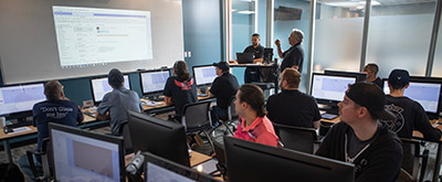
With a customized Stiles University course, we can provide expert training for your team, on-location. Whether it's programming, operation or maintenance, we want to help you train your personnel to meet your production goals efficiently and effectively.
-

Experience the trusted workforce development training and machinery knowledge you rely on from Stiles University, now at your convenience. With technology changing every day and new methods being developed constantly, Stiles University Online has the latest information and training content available at your fingertips.
-
-
-

Do you want to produce more efficiently? Processes and flows are key. We optimize these together with you, re-organize them and make sure that you reduce your lead time and save costs. This enables you to implement customized manufacturing and achieve your business goals.
-
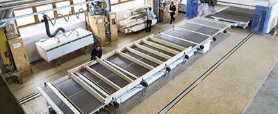
Industrialized construction is evolving. Automation, robotics and advanced technology are raising the level of productivity, efficiency and precision for builders in North America.
-
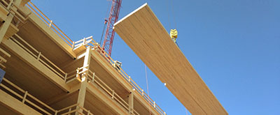
Stiles Machinery is at the forefront of providing technology and machining for producing high quality mass timber. Automated solutions for your mass timber production can increase your manufacturing quality and productivity.
-
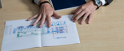
Project management services from Stiles make it easy to streamline your entire project— from concept and consultation to integration and implementation.
-

-
-
-
-
-
-
With a customized Stiles University course, we can provide expert training for your team, on-location. Whether it's programming, operation or maintenance, we want to help you train your personnel to meet your production goals efficiently and effectively.
-
Experience the trusted workforce development training and machinery knowledge you rely on from Stiles University, now at your convenience. With technology changing every day and new methods being developed constantly, Stiles University Online has the latest information and training content available at your fingertips.
-
-
-
Do you want to produce more efficiently? Processes and flows are key. We optimize these together with you, re-organize them and make sure that you reduce your lead time and save costs. This enables you to implement customized manufacturing and achieve your business goals.
-
Industrialized construction is evolving. Automation, robotics and advanced technology are raising the level of productivity, efficiency and precision for builders in North America.
-
Stiles Machinery is at the forefront of providing technology and machining for producing high quality mass timber. Automated solutions for your mass timber production can increase your manufacturing quality and productivity.
-
Project management services from Stiles make it easy to streamline your entire project— from concept and consultation to integration and implementation.
-
What Is 5 Axis Machining and How Does It Work?
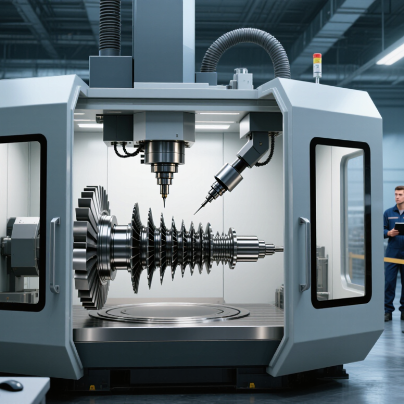
5 axis machining allows a cutting tool to move along three linear axes while rotating around two additional axes. This movement lets manufacturers reach complex surfaces from multiple directions. A turbine blade, medical implant, or aerospace bracket can often be machined with fewer setups. That matters because every repositioning can introduce alignment errors.
The process begins with a precise CAD model and a carefully prepared CAM program. The software calculates toolpaths, cutting angles, feed rates, and collision risks. During machining, the table or spindle rotates while the tool removes material from a secured workpiece. Skilled operators still monitor tool wear, workholding, coolant flow, and surface finish. Automation helps, but it does not replace judgment.
The details vary.
Not every five-axis machine behaves the same way. Some use a tilting rotary table, while others rotate the spindle head. These configurations affect reach, rigidity, programming, and achievable accuracy. A reliable workflow includes simulation, setup verification, trial cuts, and dimensional inspection using calibrated equipment.
In practice, 5 axis machining can reduce fixture changes and improve access to difficult features. However, it may also increase programming complexity, machine costs, and the risk of subtle tool collisions. Even experienced teams can miss an issue when a tool rotates behind a part. That limitation deserves attention. Understanding how the axes interact provides a stronger foundation for selecting machines, planning production, and judging whether five-axis processing truly fits a project.
What Is 5-Axis Machining?
What Is 5-Axis Machining?
5-axis machining uses three linear axes and two rotary axes to shape a part from several directions. The linear axes move along X, Y, and Z. Rotary axes tilt or turn the cutting tool, the workpiece, or both. This arrangement lets one machine reach angled faces, deep cavities, and curved surfaces with fewer setups.
The workpiece stays put. That changes everything.
A programmer can maintain a better tool angle across a contoured surface. Cutting becomes smoother, and fewer repositioning steps can reduce alignment errors. For example, a turbine-style component may require only one main setup instead of several fixture changes. However, five-axis machining is not automatically faster. Poor tool paths, weak fixturing, or an incorrect postprocessor can create collisions and scrap. That uncomfortable detail deserves attention.
Grand View Research estimated the global CNC machine market at USD 83.99 billion in 2022. Its 2023 report forecast a 9.5% compound annual growth rate through 2030. These figures cover CNC equipment broadly, not five-axis machines alone. Still, they show growing demand for automated, flexible production. In practice, the best results depend on machine calibration, cutting data, simulation, and operator judgment. ISO 230-1 testing can help verify positioning accuracy, but inspection remains essential. A beautiful simulation is not proof of a perfect part.
What Is 5 Axis Machining and How Does It Work? - What Is 5-Axis Machining?
| Dimension | What It Means | Typical Data or Configuration | Practical Benefit |
|---|---|---|---|
| Number of controlled axes | The machine controls three linear movements and two rotary movements. | 5 degrees of freedom: X, Y, Z plus two rotational axes. | The cutting tool can reach a part from multiple directions. |
| Linear axes | Linear axes move the tool, workpiece, or both along straight paths. | X = left/right, Y = front/back, Z = up/down. | Provides the primary cutting envelope and depth control. |
| Rotary axes | Rotary axes tilt or rotate the tool and/or workpiece around a linear axis. | Common combinations include A + C, B + C, or A + B; the exact layout depends on the machine design. | Allows angled tool approaches and machining around complex surfaces. |
| Axis rotation range | The available rotary travel determines how far the tool or part can tilt and rotate. | Tilting axes commonly provide approximately ±90° to ±120°; continuous rotary axes may rotate beyond 360°. | A wider range improves access to undercuts and multiple faces. |
| 3+2 machining | The two rotary axes position the workpiece or tool, then the three linear axes perform the cut. | The rotary axes remain fixed during each cutting operation. | Simplifies programming while enabling machining from several fixed angles. |
| Simultaneous 5-axis machining | All five axes move together during cutting. | The tool orientation changes continuously along the programmed toolpath. | Supports complex contours, turbine-style blades, molds, and medical components. |
| Tool orientation | The cutter can remain inclined relative to the surface instead of staying perpendicular. | The cutting direction is adjusted through rotary-axis movement and CAM toolpath control. | Reduces interference and can maintain more consistent cutting conditions. |
| Workpiece access | A single setup can expose several faces of a component to the cutting tool. | Many multi-face parts can be machined with fewer repositioning operations than on a 3-axis machine. | Can reduce setup time, alignment errors, and fixture changes. |
| Undercut capability | Rotary movement allows the cutter to approach surfaces that are hidden from a fixed vertical direction. | Suitable for undercuts, deep cavities, angled holes, impellers, and sculptured surfaces. | Expands the range of geometries that can be produced in one machine. |
| Programming requirements | The machine needs coordinated motion instructions for linear travel, rotary travel, tool orientation, and collision avoidance. | CAM software generally generates the multi-axis toolpaths and post-processes them for the target control system. | Enables automated machining of complex 3D surfaces, but requires more advanced planning than 3-axis machining. |
| Compared with 3-axis machining | A 3-axis machine controls X, Y, and Z only, while a 5-axis machine adds two rotary axes. | 3-axis: 3 controlled axes; 5-axis: 5 controlled axes. | 5-axis machining generally offers greater access and flexibility, while 3-axis equipment is usually simpler to program and operate. |
| Main limitations | More axes introduce additional motion, calibration, programming, and collision-control considerations. | Performance depends on machine kinematics, workholding, tool length, spindle capability, CAM quality, and operator skill. | Higher complexity must be balanced against the part’s geometry, quantity, and required surface quality. |
Note: Rotary-axis names, travel ranges, machine envelopes, achievable tolerances, and cutting performance vary by machine configuration, tooling, material, and process conditions.
Related Posts
-

2026 How to Choose the Best 5 Axis CNC Machine for Your Needs?
-
Top Panel Saw Suppliers in China Where to Find the Best Deals?
-
Top Wood CNC Machine Benefits for Your Business and Creative Projects
-
How to Choose the Right CNC Machining Parts Supplier?
-

Top 10 Sliding Table Saw Models for Precision Woodworking Today?
-
How to Choose the Best CNC Router for Your Projects?